Overview
Industrial-Grade Air Receiver Vessels for Compressed Air Systems
Each vessel is fabricated to stabilize system pressure, reduce compressor cycling, buffer peak air demand, and protect downstream pneumatic equipment.
With fabrication facilities in Sachin GIDC, Surat, NESF delivers air receiver vessels in vertical and horizontal configurations, custom-built to your design pressure, capacity, and inspection requirements.
Share your compressor specifications and plant air demand profile with NESF, and the team will recommend an appropriate vessel volume and fabrication scope.
- Capacity
- 50 litres to 50,000+ litres
- Design Pressure
- Up to 25 bar g, higher on request
- Orientation
- Vertical or horizontal
- Location
- Sachin GIDC, Surat
What Is an Air Receiver Vessel?
An air receiver vessel is a pressure vessel used in compressed air systems to store pressurized air between the compressor and the point of use. It acts as a buffer reservoir that absorbs demand fluctuations, prevents the compressor from short-cycling, and allows moisture and oil to settle before the air reaches process equipment.
Air receiver vessels are a critical component in any industrial compressed air network, from textile mills and auto plants to chemical facilities and food processing units. Proper sizing and fabrication quality directly impact compressor life, air quality, and system uptime.
Details
Why Choose NESF as Your Air Receiver Vessel Manufacturer?
Custom Fabrication to Your Exact Specification
NESF does not manufacture standard off-the-shelf vessels. Every air receiver vessel is fabricated to your design pressure, operating temperature, capacity requirement, nozzle configuration, and inspection standard.
Whether you need a 500-litre skid-mounted vertical vessel or a 10,000-litre horizontal air storage tank with a manhole and multiple nozzles, NESF builds it to drawing.
Qualified Welding and Disciplined QA/QC
All fabrication at NESF follows qualified welding procedures with stage-wise inspection. Welder qualification records are maintained, and fit-up checks are performed before every weld.
NDT options include Dye Penetrant Testing (DPT), Magnetic Particle Testing (MPT), Ultrasonic Testing (UT), and Radiographic Testing (RT) as required by your specification or applicable code.
Hydro and Pneumatic Testing
Every air receiver vessel undergoes hydraulic or pneumatic pressure testing before dispatch. Test pressures, test media, and acceptance criteria are documented in the inspection report provided with the vessel.
Traceable Materials and Documentation
Material traceability is maintained from procurement to delivery. Mill test certificates (MTCs), heat numbers, and dimensional inspection reports are part of the standard documentation package.
NESF can provide full quality dossiers including QAP, ITP, and test certificates for critical orders.
IS / ASME / IBR-Compliant Fabrication
NESF fabricates air receiver vessels in compliance with applicable Indian and international codes including IS 2825, ASME Section VIII Div 1, and IBR where applicable.
Third-party inspection from BVIS, SGS, Lloyds, or client-appointed inspectors is accommodated on request.
Technical Data
Air Receiver Vessel Technical Specifications
| Parameter | Range / Details |
|---|---|
| Capacity / Volume | 50 litres to 50,000+ litres (custom) |
| Design Pressure | Up to 25 bar g (higher on request) |
| Operating Temperature | -10 C to 200 C |
| Orientation | Vertical or Horizontal |
| Material of Construction | IS 2062 Carbon Steel, SA 516 Gr. 70, SS 304 / 316 for corrosive service |
| Shell Thickness | As per design calculation, with corrosion allowance included |
| Nozzle Configuration | Inlet, outlet, drain, vent, safety valve, pressure gauge, NRV, manhole / handhole |
| Supports | Saddle supports for horizontal vessels; leg supports or skirt base for vertical vessels |
| Surface Finish | Shot blasting with primer and enamel / epoxy paint as agreed |
| Applicable Codes | IS 2825, ASME Sec VIII Div 1, IBR if applicable |
| Testing | Hydrostatic / Pneumatic as per applicable code |
| NDT Options | DPT, MPT, UT, RT as specified |
| Documentation | GA Drawing, ITP, QAP, MTCs, Hydro Test Report, Dimensional Report |
Details
Industries and Applications
NESF air receiver vessels are supplied to a wide range of industries where compressed air systems are critical to plant operations.
Textile and Garment Industry
- Air receiver vessels for loom machines, air-jet weaving, and pneumatic clamping.
- Buffer storage to manage varying demand from multiple pneumatic tools.
Automotive and Auto Ancillaries
- Compressed air storage for painting booths, assembly line pneumatics, and robotic fixtures.
- High-cycle duty vessels with robust drain and safety valve configuration.
Chemical and Petrochemical Plants
- Stainless steel air receiver vessels for corrosive or clean-room compressed air.
- IBR-compliant vessels with third-party inspection for plant insurance requirements.
Food and Beverage Processing
- SS 304 / 316 vessels for hygienic compressed air service.
- Internal lining or passivation on request.
General Manufacturing and Engineering Plants
- Medium-pressure air storage for compressor rooms in fabrication shops.
- Retrofit vessels to expand existing compressed air system capacity.
Infrastructure and EPC Projects
- Skid-mounted air receiver packages for utility stations.
- Multiple vessel assemblies with interconnecting pipework.
Details
Construction and Configuration Options
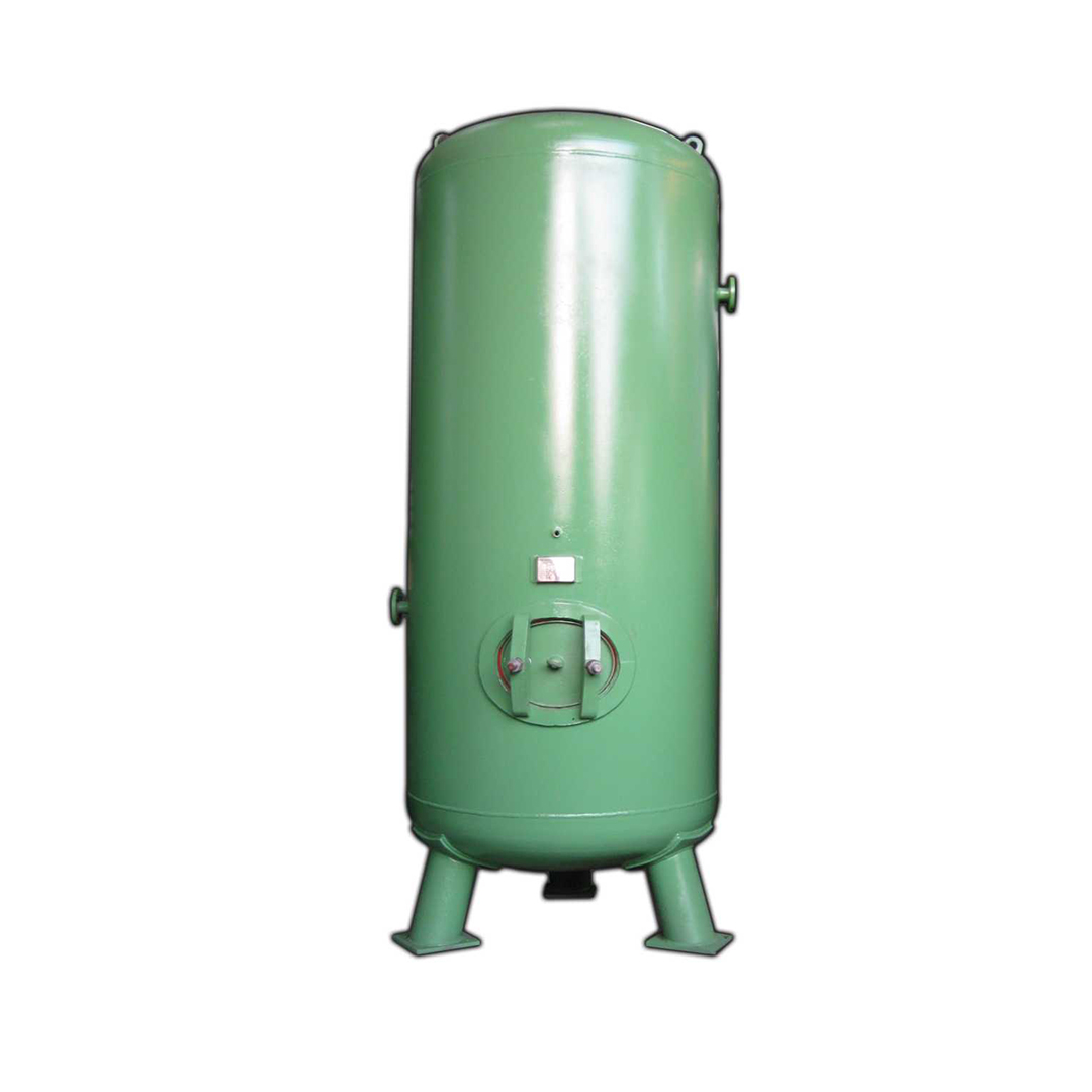
Vertical Air Receiver Vessel
Vertical orientation is the standard configuration for most plant rooms due to its compact floor footprint. NESF fabricates vertical air receiver tanks with leg supports or skirt base, dished ends such as torispherical or hemispherical as per design, and a full nozzle set.
The nozzle set can include top inlet, side outlet, bottom drain, safety valve branch, pressure gauge connection, and handhole or manhole for internal inspection.
Horizontal Air Receiver Vessel
Horizontal air receiver tanks are preferred where headroom is limited or where the vessel needs to be installed outdoors on a structural frame or skid.
NESF fabricates horizontal vessels with saddle supports designed and positioned per ASME / IS norms, with proper reinforcement on the shell.
Standard Nozzle Set
- Air inlet from compressor.
- Air outlet to distribution network.
- Safety Relief Valve (SRV) branch.
- Pressure Gauge (PG) connection.
- Condensate drain with isolating valve.
- Vent valve nozzle.
- Handhole for vessels up to 600mm diameter or manhole for larger vessels.
- NRV / check valve connection on inlet.
Accessories and Fittings - Optional Supply
- Safety relief valve calibrated to set pressure.
- Bourdon tube pressure gauge with syphon.
- Automatic drain valve, float or timer type.
- Pressure switch / transmitter tapping.
- Isolation ball valves on all nozzles.
- Sight glass for condensate level.
Details
Quality Assurance and Testing
NESF follows a structured QA/QC framework for all pressure vessel fabrication.
Pre-Fabrication
- Material traceability with MTCs verified against order specification before cutting.
- Dimensional check of incoming plates, pipes, and forgings.
- Welding Procedure Specification (WPS) reviewed and qualified.
- Welder qualification records (WQR/WPQ) maintained.
In-Process Inspection
- Fit-up check before root pass on all pressure-boundary welds.
- Visual inspection of welds after each pass.
- Stage-wise dimensional checks against approved drawing.
- Heat number stamping and material identification maintained throughout.
Final Inspection and Testing
- Hydrostatic test at 1.5x design pressure or as per applicable code.
- NDT including DPT on all nozzle welds; RT or UT on shell seams as specified.
- Dimensional check against GA drawing.
- Surface preparation and paint DFT measurement.
- Final visual inspection.
Documents Provided
- General Arrangement (GA) Drawing.
- Material Test Certificates (MTCs) with heat traceability.
- Weld Map and Weld Summary.
- NDT Reports including DPT, RT, and UT as applicable.
- Hydrostatic / Pneumatic Test Report.
- Dimensional Inspection Report.
- QAP and ITP for inspected orders.
- Paint / coating system records.
- Third-party inspection certificate if TPI is appointed.
Related Products
Request a Quote for Air Receiver Vessel Fabrication
To receive a competitive quotation, share the following details with NESF.
- Design pressure in bar g and operating pressure.
- Required vessel capacity / volume in litres or m3.
- Orientation - vertical or horizontal.
- Material of construction preference.
- Applicable code such as IS 2825, ASME Sec VIII, or IBR.
- Nozzle list and accessories required.
- Inspection requirements, including in-house, TPI, or IBR.
- Delivery location and required lead time.
FAQ
Frequently Asked Questions
Quick answers about sizing, materials, inspection, lead time, and supply scope for this product.
What is the standard design pressure for an air receiver vessel?
Most industrial compressed air systems operate between 7 and 10 bar g. NESF fabricates air receiver vessels up to 25 bar g as standard, with higher-pressure vessels available on request based on design and wall thickness calculations.
What size air receiver vessel do I need for my compressor?
A general rule of thumb is to size the air receiver at 6-10 times the compressor's free air delivery (FAD) in litres per minute. However, correct sizing depends on system pressure, compressor duty cycle, peak demand, and downstream tool consumption. Share your compressor specifications and plant air demand profile with NESF and the team will recommend an appropriate vessel volume.
What materials are used for air receiver vessel fabrication?
Carbon steel such as IS 2062 Gr. B or SA 516 Gr. 70 is standard for most industrial air service. Stainless steel such as SS 304 or SS 316 is used where moisture content, cleanliness, or corrosion requirements demand it, such as food processing, pharmaceutical, or offshore applications.
Is NESF a certified pressure vessel manufacturer?
NESF fabricates pressure vessels in compliance with IS 2825 and ASME Section VIII Div 1 where required. Third-party inspection from BVIS, SGS, Lloyds, or client-nominated inspection agencies is accommodated. Specific certifications can be discussed based on your order requirements.
What is the minimum and maximum vessel capacity NESF manufactures?
NESF fabricates air receiver vessels from 50 litres to 50,000+ litres. Larger multi-vessel battery arrangements are also possible. Share your project requirement and NESF will confirm the feasibility and fabrication scope.
How long does it take to manufacture an air receiver vessel?
Lead time depends on vessel size, complexity, material availability, and inspection requirements. Standard vessels typically have a lead time of 2-4 weeks. Larger vessels with third-party inspection requirements may take 4-8 weeks. NESF will confirm lead time at the time of order placement.
Can NESF supply the vessel with fittings, valves, and accessories?
Yes. NESF can supply air receiver vessels complete with safety relief valves, pressure gauges, drain valves, NRVs, and isolation valves as per your BOM or P&ID. Accessory sourcing and assembly on the vessel nozzles can be included in the supply scope.
Fabrication Support
Built around your drawings, duty conditions, and inspection needs.
Share specifications, P&ID, MOC, dimensions, and testing requirements. The NESF team can align fabrication, documentation, and delivery around your project.
Contact Details
- Call / WhatsApp
- +91 95740 11132
- Address
- Plot No. 1022, Cross Road No. 87, Sachin GIDC, Surat - 394230
Enquiry Form
Request a Quote for Air Receiver Vessel Fabrication
Share design pressure, capacity, orientation, MOC, code, nozzle list, inspection requirements, and delivery location.